Engineering records / Engineering record / ROOF-BEARINGS-R1
Roof Bearings R1.
Geometry, analysis and remaining engineering work for Roof Bearings R1.
Retained development study. Dimensions, names and checks belong to this revision—not automatically to the retrofit-only product. Manufactured tank shells are deferred. No installation instruction, certification or manufacturing release is represented.
The source reasoning
Why this detail was investigated.
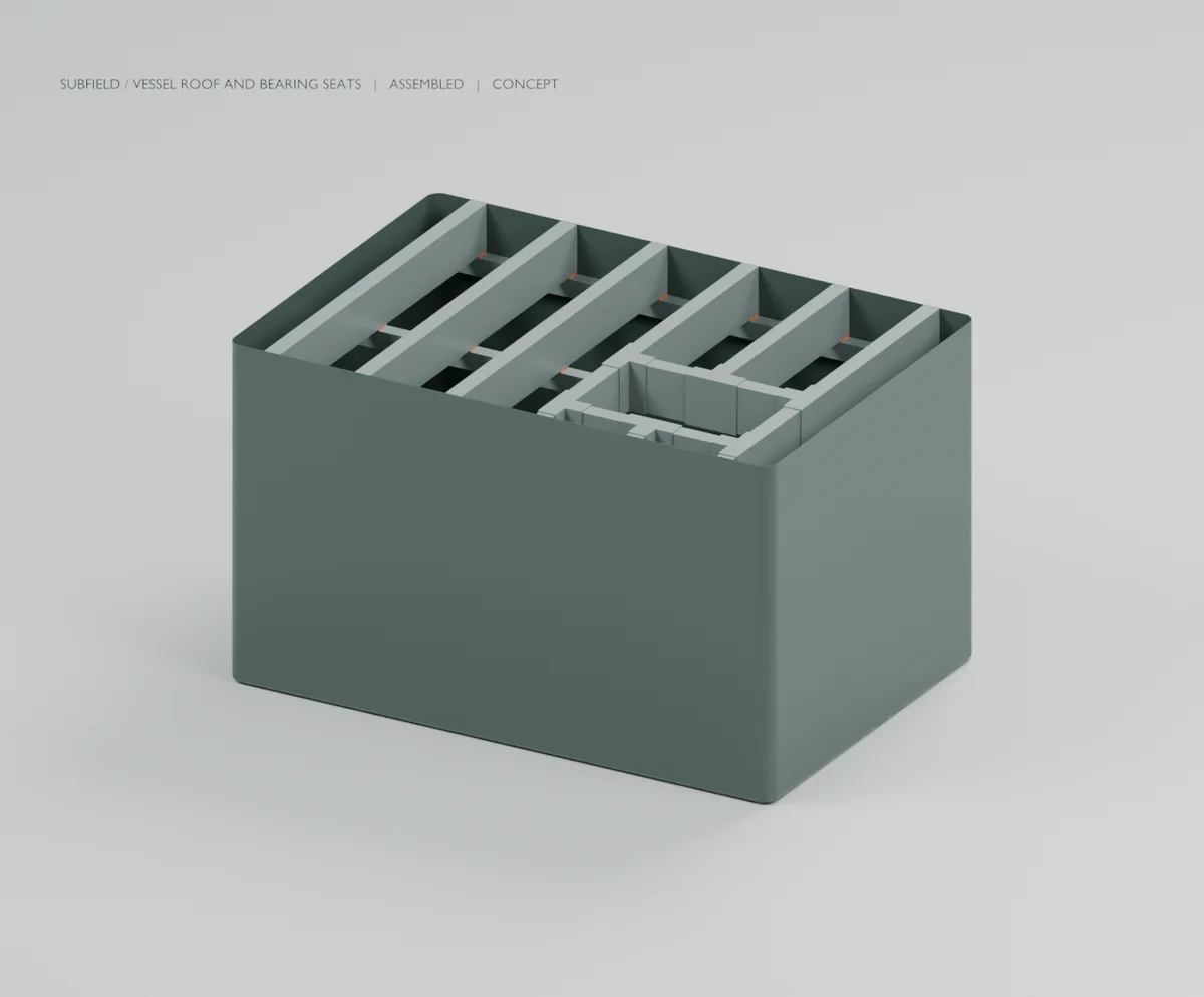
This candidate resolves the prior roof-member/skin intersections. Each outside member end is shortened 5 mm, leaving 2 mm nominal clearance to the 3 mm skin. Three longitudinal support rails and 18 separate seats carry the roof contact into an explicit support interface.
Read the research and limits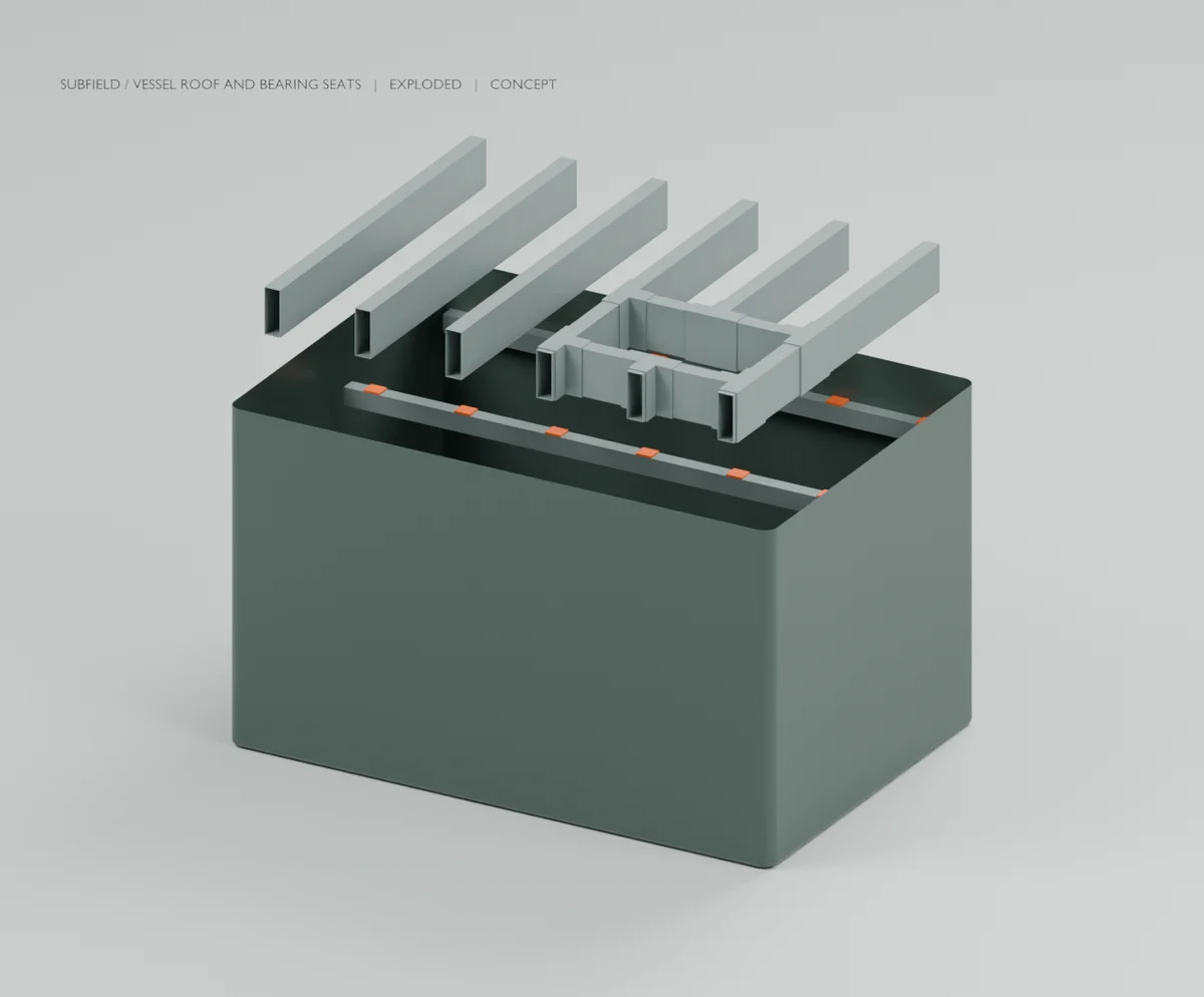
Research record
The detail behind
the study.
Source-linked work for this revision. Reported checks describe the stated model or test; physical qualification and applicability to the current retrofit remain separate.
This candidate resolves the prior roof-member/skin intersections. Each outside member end is shortened 5 mm, leaving 2 mm nominal clearance to the 3 mm skin. Three longitudinal support rails and 18 separate seats carry the roof contact into an explicit support interface.
The rail section (80 × 100 × 3 mm), rail length (2900 mm) and seat blanks (90 × 80 × 10 mm) are preliminary engineering choices. Seat relief follows the local joint overwrap, preserving contact without intersecting its material. There are 43 separate solids in the exported assembly.
This is not a completed load path. The rails still need permanent supports to the base, and the roof requires positive restraints. Bearing stresses, local crush, rail bending/buckling, joints, materials and tolerances remain to be designed. No load is credited to the thin skin.
The bearing centers moved inward from the old grillage support lines. Previous roof reaction and movement results therefore do not verify this configuration. The next structural model must use the revised support geometry and its flexibility.
The STEP file preserves the fitted assembly. Blender's exploded view raises the roof for inspection; it does not demonstrate a safe lifting procedure, lifting attachments, release of restraints or service reach. The recorded fit checks cover geometry only.
Source and revision record
Source: roof-bearings-r1/READ-ME.md
Source SHA-256: 66d3babab5b07f3a0fb1bb5d0832823a171fb995e25e1dd296c36f81a8ee376c
Geometry and images describe this development revision. Current product ratings and manufacturing release require separate qualification.
Return to the current product.
Explore the retrofit-only platform and its compatibility, installation and service objectives.
Explore the retrofit