Engineering records / Engineering record / CABLE-RING-INSTALLATION-AUDIT
Cable Ring Installation Audit.
Geometry, analysis and remaining engineering work for Cable Ring Installation Audit.
Retained development study. Dimensions, names and checks belong to this revision—not automatically to the retrofit-only product. Manufactured tank shells are deferred. No installation instruction, certification or manufacturing release is represented.
The source reasoning
Why this detail was investigated.
Finding: R2 has positive nominal collar capture, but its retaining ring does not have a demonstrated installation process. A concentric expansion path over the keys fails the available collar-space check. The earlier successful tests cover the collar installation with the ring absent, not installation of the ring itself.
Read the research and limitsResearch record
The detail behind
the study.
Source-linked work for this revision. Reported checks describe the stated model or test; physical qualification and applicability to the current retrofit remain separate.
Cable retaining-ring installation audit
Finding: R2 has positive nominal collar capture, but its retaining ring does not have a demonstrated installation process. A concentric expansion path over the keys fails the available collar-space check. The earlier successful tests cover the collar installation with the ring absent, not installation of the ring itself.
Measured and calculated evidence
The actual key vertices reach radius 17.564168 mm. Adding an explicit study allowance of 0.10 mm requires an expanded ring inner radius of 17.664168 mm. The collar bore radius is nominally 20.30 mm.
| Ring | Wall used for screen | Expanded outer radius | Clearance to nominal collar bore |
|---|---|---|---|
| R2 custom C-ring | 3.00 mm | 20.664168 mm | **−0.364168 mm** |
| VSM-32 candidate | 2.34 mm, catalog maximum | 20.004168 mm | **+0.295832 mm** |
| DNS-32 comparison | 3.35 mm, catalog maximum | 21.014168 mm | **−0.714168 mm** |
The current unexpanded ring also intersects the body along the sampled axial extraction/insertion path. See audit.json for individual overlap volumes. The three solids in comparison-envelopes.step are diagnostic expanded annuli, not supplier ring CAD or physically simulated deformation states.
This screen assumes concentric expansion with preserved radial wall thickness. It does not rule out every nonconcentric/spiral assembly method, establish allowable strain, or include a complete tolerance stack. A positive space result is necessary for this proposed path, not sufficient proof of installation.
Smalley's VSM-32 is an external single-turn ring for a 32 mm shaft. Its published groove diameter is 30.88 ±0.10 mm, groove width 0.79 +0.08/−0.00 mm, ring thickness 0.64 ±0.04 mm, radial wall 2.24 ±0.10 mm and free ID 30.57 +0.00/−0.38 mm. These dimensions make it a candidate for further development, not a drop-in substitute for R2's 30.4 mm diameter, 1.9 mm wide groove. Source: VSM-32 product data.
The two-turn DNS-32 has a 3.25 ±0.10 mm radial wall and fails this concentric space screen. Its alternative installation method could be evaluated separately, but it is not selected here. Source: DNS-32 product data.
Smalley describes winding spiral rings into the groove and inspecting seating. This offers an installation-method lead; it does not prove access through our enclosing collar. Source: manual installation.
The supplier calls for installation-stress analysis for custom rings or custom tooling. Our keys require passage beyond a plain 32 mm shaft, so the standard-shaft exemption must not be presumed to apply. Evaluate material, installation method, repeated service and actual retention load before selecting the part. Source: installation stress analysis.
1. Develop the VSM-32 groove and collar stack as a separate revision, accounting for the catalog groove/ring tolerances and actual body/collar process tolerances. Preserve the seal groove and contact/key engagement sequence. 2. Obtain exact supplier geometry or establish a verified controlled interface drawing. The public site requires a contact-information form for CAD access; no form was submitted and no supplier was contacted. A catalog-derived envelope must remain labeled as such. 3. Model the actual installation tool/access or spiral insertion path. Confirm permitted expansion and ring seating with the selected material and supplier method. The current 0.296 mm envelope clearance is not automatically tool clearance. 4. Establish the connector pull/torque/handling requirement and calculate/test the complete load path through collar, ring, body groove and mating studs. Catalog load figures do not rate the Subfield assembly or its unselected body material.
The current complete product model remains R2. No supplier ring has been installed in it, and manufacturing release remains false. The audit adds evidence of an unresolved assembly operation rather than masking it with another passing fit check.
Run the supplied audit.py from its original workspace location work/cable-ring-installation-audit/ with the locked CAD runtime. It consumes current CAD/cable_retention_r2.py and subfield_cable_r1.py; source hashes are in audit.json. The diagnostic STEP has three valid reimported solids. No production geometry was modified during this audit.
Source and revision record
Source: cable-ring-installation-audit/README.md
Source SHA-256: ec5ada4b1632ac4671df18f317dc7334df973455abeda5194674b83a59a47e82
Geometry and images describe this development revision. Current product ratings and manufacturing release require separate qualification.
Keep exploring the research.
Engineering records / Engineering record
Cable Seal Audit
Geometry, analysis and remaining engineering work for Cable Seal Audit.
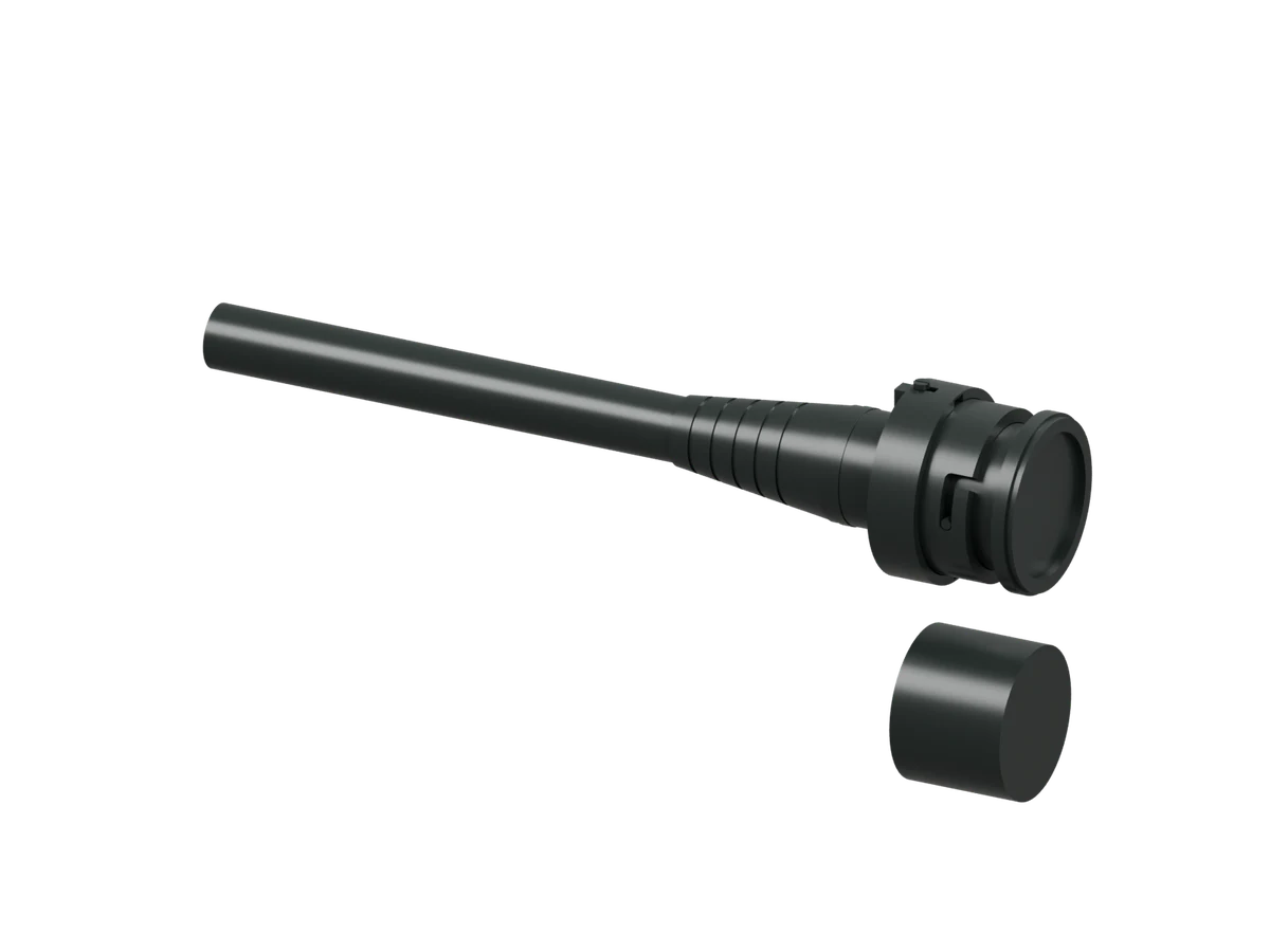
Connections / Development CAD
Link threaded stops
Inspect the latest complete termination geometry with modeled threaded stops.
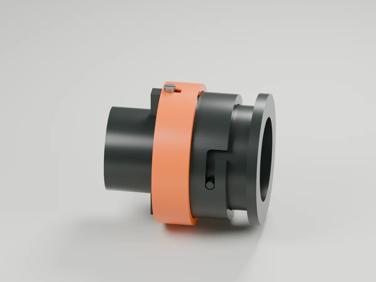
Connections / Design study
Link sleeve stops
Radial shoulder stops capture the sleeve around a proposed 3 mm release motion.
Return to the current product.
Explore the retrofit-only platform and its compatibility, installation and service objectives.
Explore the retrofit