Engineering records / Engineering record / FRAME-JOINTS-R1
Frame Joints R1.
Geometry, analysis and remaining engineering work for Frame Joints R1.
Retained development study. Dimensions, names and checks belong to this revision—not automatically to the retrofit-only product. Manufactured tank shells are deferred. No installation instruction, certification or manufacturing release is represented.

The source reasoning
Why this detail was investigated.
Status: detailed joint geometry for engineering review; not a manufacturing release.
Read the research and limits

Research record
The detail behind
the study.
Source-linked work for this revision. Reported checks describe the stated model or test; physical qualification and applicability to the current retrofit remain separate.
Subfield frame joint development package
Status: detailed joint geometry for engineering review; not a manufacturing release.
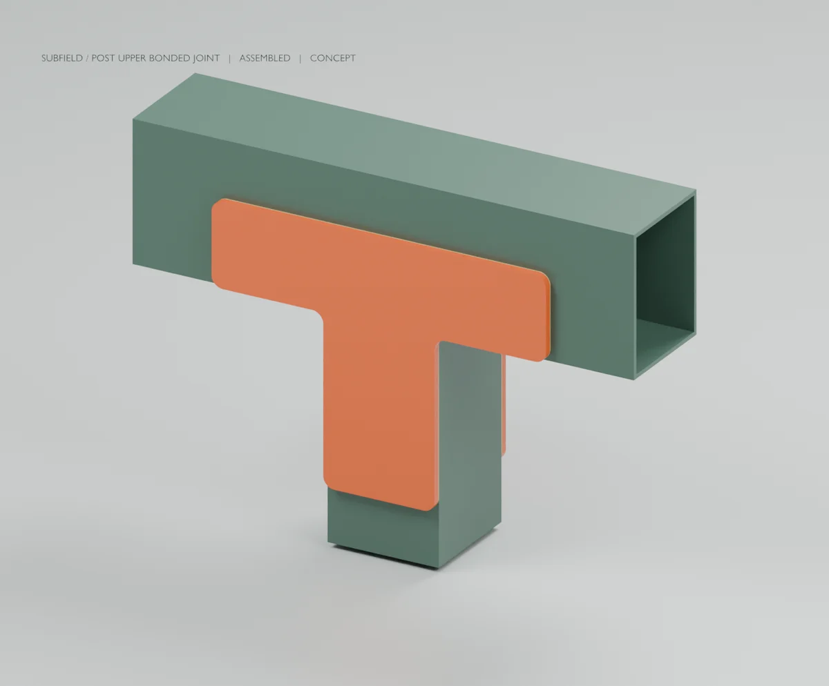
This revision adds paired bonded cheek plates at all 36 ends of the eighteen permanent posts. The complete frame STEP contains 301 separate solids, including 216 new plate, spacer and bond solids. The tank skin, roof frame and lower structure remain incomplete as a finished product.
- 72 flat cheek plates, nominally 5 mm thick, with 8 mm outline radii. - 36 separate 4.5 mm lower-joint spacers and 108 modeled 0.5 mm bond layers. - Seven STEP/DXF profile files, with quantities in preliminary-plate-cut-list.csv. The three spacer variants have matching outlines but retain location-specific IDs. - Upper plates overlap 120 mm of post and 60 mm of the rail. Lower plates use the same overlap depths, with shortened outer arms to stay within the member end. - Both outer support rows move 6 mm inward to Y = -999.5 and +999.5 mm. Their seats and floor shoes are rebuilt at that position. Minimum modeled upper plate-to-skin clearance is 2.50 mm. - Roof bearing heights and member sections are unchanged. Both moving service envelopes and assembled representative modules clear the current frame and joints.
The joints add approximately 16.14 kg (35.6 lb) using assumed densities. The incomplete assembly now totals 274.69 kg (605.6 lb). This exceeds the 500 lb objective before adding the missing roof skin, closures, risers and other permanent equipment/interfaces. The weight objective remains unresolved.
At the relocated supports, the nominal axial-cap/shear-web elastic case gives 1.431 mm maximum calculated roof movement and 61.44 kN peak post reaction. Halving all modeled elastic stiffnesses gives 2.861 mm movement. These calculations omit joint flexibility, rail/base/soil compliance and frame sway; they do not establish the physical joint capacity or a post effective-length factor.
- vessel-frame-joints.step: complete current geometric assembly. - UPPER/LOWER profile STEP and DXF files: separate flat stock shapes, millimetres. - upper and lower folders: assembled/exploded PNG views, animated GLB and Blender inspection files. These show clipped stock for visibility; the complete STEP retains the full frame. - joint-record.json: interfaces, bond areas, clearance/contact checks and mass assumptions. - relocated-roof-analysis.json: linear reaction/deflection calculation for the new support positions. - dxf-validation.json: all seven profiles reimported as one closed outline; units and area-to-STEP volume agree. - current-cad-source.zip: current executable source, parameters, tests and pinned dependencies.
The full CAD test suite passed: 66 tests in 25.44 seconds. The assembly generator passed 670 checks, including contact, all-part noninterference, current service envelopes, relocated reaction-node positions and STEP reimport. Rendering completed in Blender 5.2.1 and the assembled upper and exploded lower views were inspected. These are geometry and numerical checks, not physical qualification.
Remaining before fabrication release
Plate laminate, adhesive, bond preparation, cure, environmental protection, manufacturing tolerances and inspection acceptance are not selected or qualified. The bond areas are geometric quantities, not strength values. Design combined shear/peel and adherend bending, delamination, imperfections and load cycling. Establish the whole-frame lateral restraint path and base/floor attachment; paired plates alone do not prove stability. Tube end closure/drainage and cleanability also remain unresolved. The tank still lacks several required components and a complete manufacturing drawing/BOM set.
Extract current-cad-source.zip. From its cad folder:
The joint generator builds service envelopes from the current shared placement functions. Older roof/post analysis packages remain snapshots of their prior support geometry; do not substitute their coordinates for this revision.
Source and revision record
Source: frame-joints-r1/READ-ME.md
Source SHA-256: 33d3e504ab9f4cde51ddcabf1b80766c7644972538df063d9beb0ea032368312
Geometry and images describe this development revision. Current product ratings and manufacturing release require separate qualification.
Return to the current product.
Explore the retrofit-only platform and its compatibility, installation and service objectives.
Explore the retrofit