Engineering records / Engineering record / FORMED-VESSEL-R1
Formed Vessel R1.
Geometry, analysis and remaining engineering work for Formed Vessel R1.
Retained development study. Dimensions, names and checks belong to this revision—not automatically to the retrofit-only product. Manufactured tank shells are deferred. No installation instruction, certification or manufacturing release is represented.
The source reasoning
Why this detail was investigated.
Status: preliminary CAD alternative for engineering development. Not a fabrication release.
Read the research and limits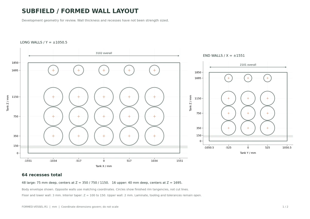
Research record
The detail behind
the study.
Source-linked work for this revision. Reported checks describe the stated model or test; physical qualification and applicability to the current retrofit remain separate.
Subfield formed vessel development package
Status: preliminary CAD alternative for engineering development. Not a fabrication release.
This alternative replaces the previous 3 mm flat upper wall with a 2 mm normally offset formed wall. It retains the 3 mm floor and lower wall, transitions internally from 3 to 2 mm between Z = 100 and 150, and fits the current jointed frame. The prior flat-wall package remains a separate design alternative. Neither wall has a demonstrated pressure capacity.
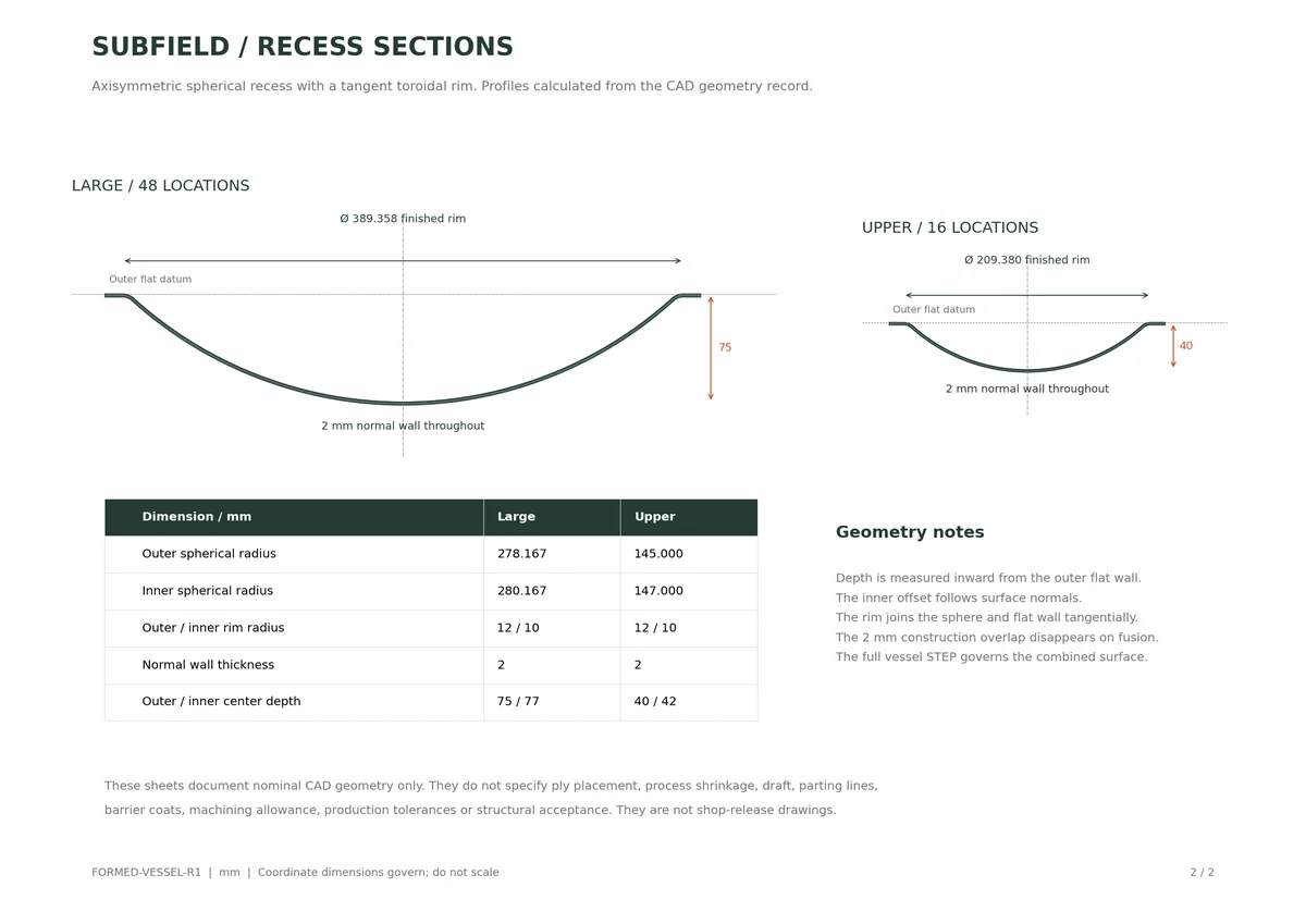
- Body envelope: 3102 × 2101 × 1850 mm. - 48 large recesses, 75 mm outer depth, at Z = 350 / 750 / 1150 mm. - 16 upper recesses, 40 mm outer depth, at Z = 1695 mm. - Finished rim diameters: 389.358 and 209.380 mm. Each surface joins a spherical region, a tangent toroidal rim and the flat wall. - Constant 2 mm normal thickness through each recess; outer rim radius 12 mm and inner radius 10 mm. - Long-wall center coordinates X = -1034 / -517 / 0 / 517 / 1034 mm. End-wall centers Y = -525 / 0 / 525 mm. Opposite walls match. - The upper row was moved above the support rails. Its complete construction-patch bounding envelope has over 8 mm vertical clearance from the rail top. - The combined STEP has 301 separate solids. The vessel skin itself is one closed solid. No cutting seams or separate insert joints are implied by the construction patches.
| Quantity | kg | lb |
|---|---|---|
| Previous flat-wall skin | 118.64 | 261.6 |
| Formed-wall skin | 93.84 | 206.9 |
| Reduction | 24.80 | 54.7 |
| Incomplete formed vessel and jointed frame | 249.89 | 550.9 |
The takeoff uses assumed composite density 1560 kg/m³ and adhesive density 1200 kg/m³. Reducing the nominal wall thickness is responsible for the weight reduction; the recesses are not proven to permit that reduction. The incomplete assembly exceeds the 500 lb target by 50.9 lb. Roof skin, closures, risers and other required components will add weight. This is not the final tank-only weight.
The study liquid surface remains Z = 1403 mm. The gross cavity below it holds 2343.02 US gal. The modeled frame solids displace 12.31 gal. Treating hollow posts and base members as closed adds 59.24 gal displacement, leaving 2271.48 gal before missing equipment and operational allowances. Flooding or closure of those members has not been designed.
For comparison with R0.1's total 10% displacement allowance, this gross cavity allocates 234.30 gal to displacement. The modeled closed-frame scenario consumes 71.55 gal of it, leaving 162.75 gal unallocated. Applying the full total allowance leaves 2108.72 gal. The allowance is not automatically deducted again from the already measured-frame result. See capacity-accounting.json for this arithmetic.
These figures do not establish rated usable capacity. Process equipment, partitions, final inverts, working levels and operational dead volumes are incomplete.
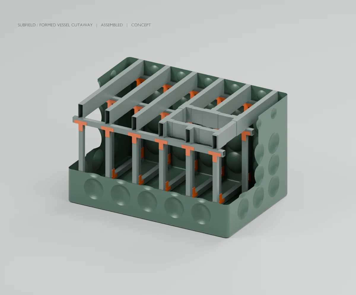
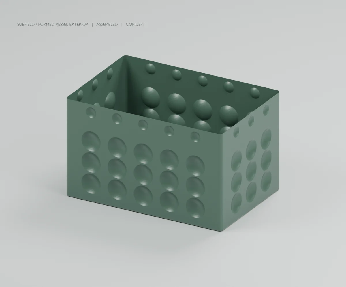
- formed-vessel-frame.step — complete current 301-solid assembly for CAD inspection. - formed-lower-vessel.step — complete formed skin, without a visual cutaway. - formed-wall-reference-drawings.pdf — two dimensioned reference sheets: wall coordinates and exact recess profiles. Nominal geometry only; production tolerances and tooling details are not included. - large_panel-normal-thickness-reference.step and upper_panel-normal-thickness-reference.step — local panel geometry, Z outward, outer flat at Z = 0. Their construction overlap annulus is fused away in the full vessel. - exterior/ and cutaway/ — PNG, GLB and Blender review files generated from the CAD meshes. The cutaway removes part of the wall for visibility; it is not a physical opening. - liquid-before-frame-displacement.step — the liquid study solid before deducting the frame. - formed-vessel-record.json — checks, placements, mass/volume results and source hashes. - current-cad-source.zip — source, parameters, tests and pinned CAD dependencies. This includes earlier alternative generators; formed_vessel.py is the entry point for this revision. - review-tools/ — the reference drawing script; requires NumPy and Matplotlib in its Python environment.
The full CAD test suite passed: 74 tests in 21.72 seconds. The formed-vessel generator passed all 20 checks, including valid solids, STEP reimport, frame/joint noninterference and current representative wet-module service envelopes. The fixed flat-wall portion is contained inside the previous 3 mm skin, and all formed patches are separately checked against the existing frame. The previous joint package retains its stock-to-stock verification.
Both exterior and cutaway renders completed in Blender 5.2.1 and were visually inspected. The two reference sheets were inspected for legibility. Render scene hashes and source hashes match this package. These checks establish geometry and reproducibility, not structural strength or manufacturing qualification.
Resolve loads on the formed wall and intervening flat regions, internal and external pressure, local instability, joint/frame restraint, creep, impact and durability. Define the laminate and protective layers, radii acceptable to its process, ply transitions, molding draft/tool splits, cure, bonding, tolerances and inspection criteria. Complete the roof skin and closure, risers, pumpout, ports, internal process components and installation interfaces. The 1500 and 3000 gallon family members remain unsized; this package covers only the lead body envelope.
Extract current-cad-source.zip. From its cad folder:
For Blender views, invoke wet_render.py with the generated exterior-scene.json or cutaway-scene.json. Use a separate output parent folder for each scene so its GLB, Blender file and toolchain record remain distinct. The package reference sheets can be regenerated with python review-tools/formed_vessel_drawing.py --out . from this package directory.
Source and revision record
Source: formed-vessel-r1/READ-ME.md
Source SHA-256: 8c4169474acc25e0c010d8dbb5f285d8a088eb30732ae6f4b7162df999375324
Geometry and images describe this development revision. Current product ratings and manufacturing release require separate qualification.
Return to the current product.
Explore the retrofit-only platform and its compatibility, installation and service objectives.
Explore the retrofit