Connections / Design study / CABLE-RING-R3
A more defined interface.
A catalog-derived ring envelope and proposed tolerance basis advance the connector.
Retained development study. Dimensions, names and checks belong to this revision—not automatically to the retrofit-only product. Manufactured tank shells are deferred. No installation instruction, certification or manufacturing release is represented.
The source reasoning
Why this detail was investigated.
R3 replaces the custom R2 ring interface with a supplier-derived installed envelope. Installation stress, tool access and allowable endplay remain open.
Read the research and limitsResearch record
The detail behind
the study.
Source-linked work for this revision. Reported checks describe the stated model or test; physical qualification and applicability to the current retrofit remain separate.
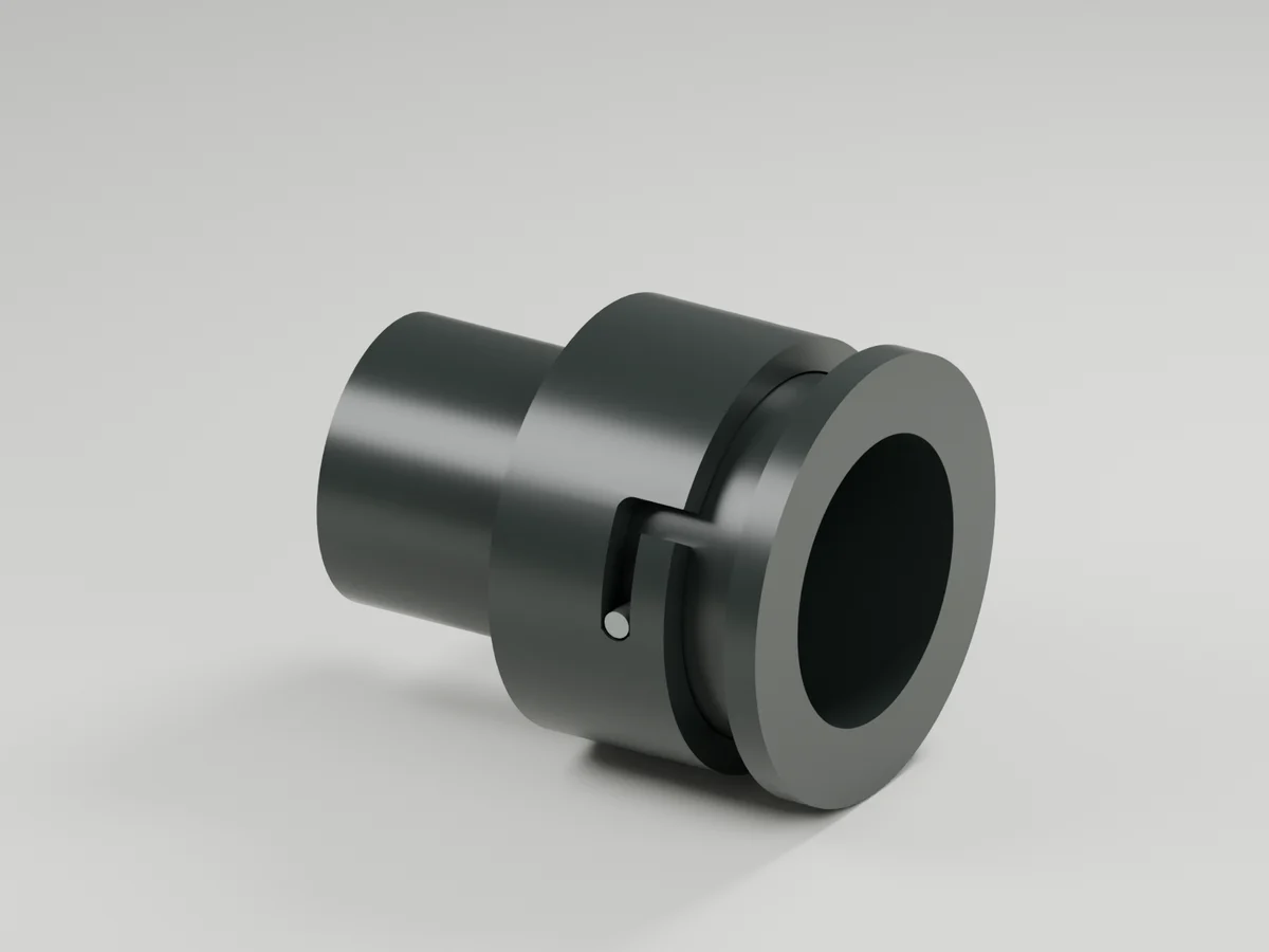
R3 replaces the R2 custom ring interface with a catalog-derived VSM-32 installed envelope and matching groove. It preserves the complete cable, connector class keys and bayonet arrangement. The ring is represented by a conservative full annulus; this is not exact supplier ring CAD, its free shape, or its installation deformation.
Supplied geometry
complete-termination.step: 457 separate cable/connector solids.
interface-envelope.step: eight mechanical interface solids.
inspection.blend / inspection.png: native CAD-derived inspection render.
The ring envelope is ID30.88, OD35.36 and thickness0.64 mm, placed at Z16.075–16.715. The body groove begins at Z16.00 and is 0.79 mm wide with a 30.88 mm root diameter. These dimensions use the Smalley VSM-32 published interface . The supplier's free ID and end shape differ from the installed annular envelope.
Proposed tolerance basis
Published ring/groove tolerances are included. Custom body/collar radial and axial face targets are ±0.05 mm; groove-start location is ±0.02 mm. These are engineering targets requiring process-capability validation, not existing supplier or factory acceptance limits. The key corner uses radial17.50±0.05 and tangential half-width1.50±0.05 mm. The internal collar radius uses20.30±0.05 mm. Body bore uses12.00±0.05 mm radius. Nominal collar flange faces remain Z14.15 and15.85; rear body shoulder Z14.00; ring relief radius18.40.
| Result across the stated ranges | mm |
|---|---|
| Minimum groove width minus maximum ring thickness | 0.110 |
| Maximum groove width minus minimum ring thickness | 0.270 |
| Minimum front clearance | 0.080 |
| Minimum rear clearance | 0.050 |
| Minimum ring-to-relief radial clearance | 0.520 |
| Minimum radial collar capture | 1.280 |
| Minimum body wall at groove | 3.340 |
| Minimum concentric installation-envelope clearance | 0.192 |
| Upper bound on combined axial float | 0.740 |
The 0.192 mm installation result includes a 0.10 mm study passage allowance. It is not tool clearance or proof that the ring tolerates the required expansion. The axial-float upper bound is an output to evaluate against allowable connector movement; no maximum permitted endplay has yet been selected.
Verification and limits
170 generation checks pass, covering applicable nominal motion/interference, groove restraint and both STEP round trips. Two focused tests pass. A separate copied-source rebuild matches all465 STEP solids by individual Boolean symmetric difference. The native Blender file was reopened and its eight visible meshes checked against CAD vertices within0.001 mm; the image was visually reviewed. The complete R3 regression passed348 tests in2006.54 seconds, terminal exit0. This run predates R4 and later tests.
Actual supplier geometry, selected material, installation stress, installation/removal access, allowable endplay, axial load and fatigue remain unresolved. The supplier's stress guidance matters because our keyed passage exceeds a plain32 mm shaft. The actual spiral installation method needs an accessible assembly sequence. Seal compression, stud attachment, detent/preload and electrical contact termination also remain unfinished.
This revision closes the oversized-ring interface mismatch at the nominal/tolerance-envelope level. It is a development candidate, not a released manufacturing design or an approved VSM-32 application.
Source and revision record
Source: cable-ring-r3/index.html
Source SHA-256: 1c9ec12ad4805d791bcb728f54685bf5ae3408c8fc52747b867f06bad19bf2bd
Geometry and images describe this development revision. Current product ratings and manufacturing release require separate qualification.
Keep exploring the research.
Engineering records / Engineering record
Cable Ring Installation Audit
Geometry, analysis and remaining engineering work for Cable Ring Installation Audit.
Engineering records / Engineering record
Cable Seal Audit
Geometry, analysis and remaining engineering work for Cable Seal Audit.
Connections / Development CAD
Link threaded stops
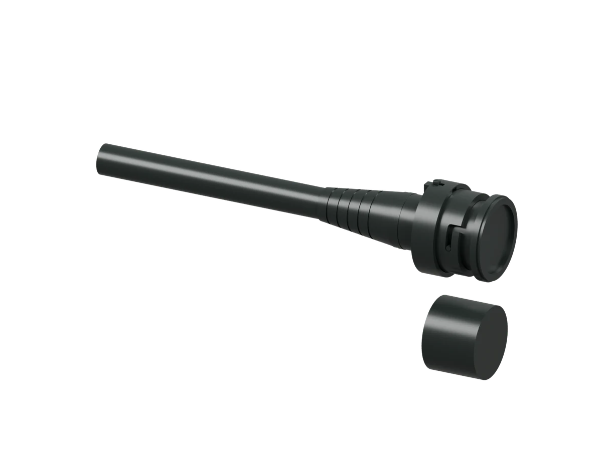
Inspect the latest complete termination geometry with modeled threaded stops.
Return to the current product.
Explore the retrofit-only platform and its compatibility, installation and service objectives.
Explore the retrofit