Tank & access / Calculated study / DUAL-ROOF-R3
Two openings. One roof model.
A connected elastic-demand study tied to the recessed-shell tank geometry.
Retained development study. Dimensions, names and checks belong to this revision—not automatically to the retrofit-only product. Manufactured tank shells are deferred. No installation instruction, certification or manufacturing release is represented.
The source reasoning
Why this detail was investigated.
Both opening frames transfer load through connected rails and bearing stations. The study compares assumptions while preserving the full applied load.
Read the research and limits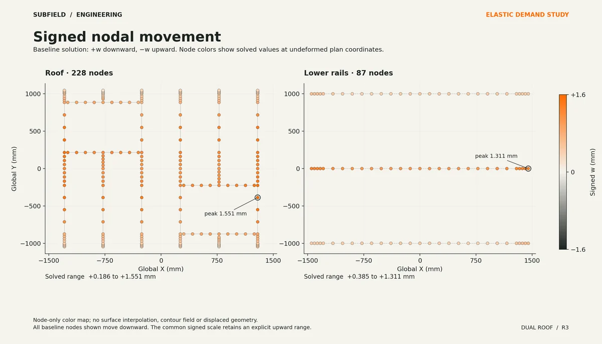
Research record
The detail behind
the study.
Source-linked work for this revision. Reported checks describe the stated model or test; physical qualification and applicability to the current retrofit remain separate.
ENGINEERING REVIEW · R3 · ELASTIC DEMAND STUDY
Elastic demand comparison. No strength, stability, containment or manufacturing qualification is established.
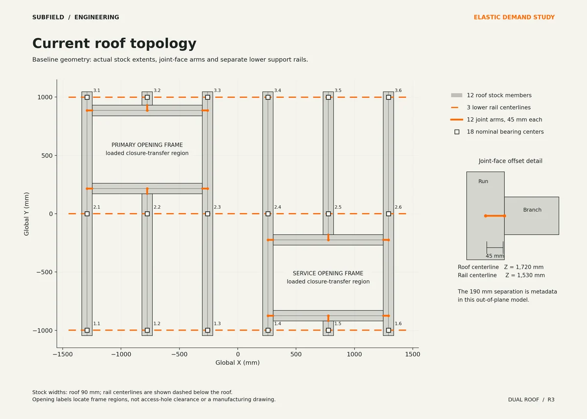
Current recessed-shell R2 geometry · 12 T joints · 18 bearing stations · 3 continuous support rails.
All values are calculated under stated elastic and support assumptions. Movement is measured from an assumed fixed post-bottom reference. These are demands, not rated performance.
What changed
The current geometry has two distinct access frames, twelve T joints, twelve roof stock members, three continuous rails and eighteen bearing/post stations. The rails connect both frame groups.
The complete 3102 × 2101 mm comparison footprint carries 101.44 kPa, including loaded closures: 661,115.11488 N downward. Both global first moments are conserved.
Explicit load recovery includes eight 45 mm header-end regions, four 45 mm cut-stub regions and twelve 5 mm fitted-end strips. The four stub regions contribute 9,440.0064 N that would be lost by loading physical stock alone.
Rigid-region routes produce the same displacements but different connection forces. Finite connection flexibility also changes response. Each exported joint row retains its concurrent signed force/moment combination.
Same-load comparisons
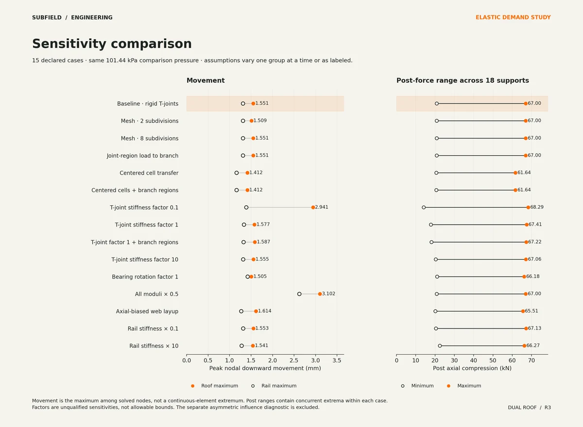
One assumption changes at a time except where the case name identifies both changes. These comparisons are not qualified upper or lower bounds.
| Case / raw result | Sampled roof movement, mm | Peak post compression, kN |
|---|---|---|
| Baseline: rigid T joints, free bearing rotation | 1.551 | 67.00 |
| Mesh: 2 subdivisions | 1.509 | 67.00 |
| Mesh: 8 subdivisions | 1.551 | 67.00 |
| Joint regions carried by branches | 1.551 | 67.00 |
| Centered tributary cells | 1.412 | 61.64 |
| Centered cells; branch regions | 1.412 | 61.64 |
| T-joint stiffness factor 0.1 | 2.941 | 68.29 |
| T-joint stiffness factor 1 | 1.577 | 67.41 |
| T-joint factor 1; branch regions | 1.587 | 67.22 |
| T-joint stiffness factor 10 | 1.555 | 67.06 |
| Bearing rotation stiffness factor 1 | 1.505 | 66.18 |
| All material moduli multiplied by 0.5 | 3.102 | 67.00 |
| Axial-biased web laminate | 1.614 | 65.51 |
| Rail stiffness multiplied by 0.1 | 1.553 | 67.13 |
| Rail stiffness multiplied by 10 | 1.541 | 66.27 |
Verification
74 focused tests, 66 analysis checks and 234 independent topology/load/action checks passed. The independent audit covers all sixteen saved cases, including the influence fixture. Twenty-one geometry source hashes and eight prior CAD evidence hashes matched current local files.
Mesh refinement compares sampled movement, all signed T-joint actions and discrete energy. Analytic beam/offset fixtures, pressure scaling and patch/remainder superposition provide independent numerical checks.
Open engineering scope
Exact CAD member axes and 45 mm joint-face offsets are used. Section stiffness is homogenized from assumed laminates; local orthotropy, bending-twisting coupling, wall buckling and strength are not solved.
Deck, ribs, skins, curbs and closures route load through explicit alternatives but their stiffness and strength are omitted.
All 18 bearings use nominal projected-area centroids and bilateral vertical compatibility. Positive compression is necessary but cannot prove pressure distribution, no lift-off or contact strength.
Baseline roof-to-rail bearing rotations are free. Finite rotational springs are unqualified sensitivities, not evidence of a positive attachment.
Each post is an axial spring to a fixed bottom reference. Post bending/buckling, rail/post joint flexibility, lower frame, floor, bedding and soil deformation remain excluded.
The 190 mm roof/rail vertical separation is metadata only in the out-of-plane model; in-plane axial/rotation coupling and geometric stiffness are excluded.
Finite T-joint springs use dimensionless member-stiffness normalizations. They are not measured joint properties or qualified bounds.
All outputs are concurrent signed elastic demand cases. No fabrication layup, joint strength, allowable, tank rating or manufacturing release is provided.
Source and revision record
Source: dual-roof-r3/index.html
Source SHA-256: 7eca6ea9aac6709a8918db0db83b0dfcf108e8e9d682bf8ab4b57bc4d046973d
Geometry and images describe this development revision. Current product ratings and manufacturing release require separate qualification.
Keep exploring the research.
Tank & access / Design study
Standard tank partitions
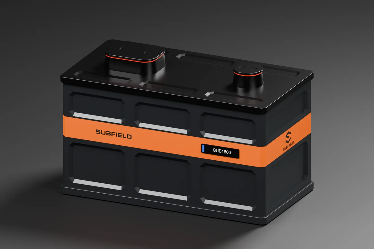
Layered partition fit studies for SUB1500 and SUB2000.
Tank & access / Design study
Two-size tank family
Four planned models, with separate 1,500- and 2,000-gallon body envelopes.
Tank & access / Calculated study
Tank capacity study
An empty-cavity calculation examines headspace and displacement reserves.
Return to the current product.
Explore the retrofit-only platform and its compatibility, installation and service objectives.
Explore the retrofit