Treatment & service / Design study / SCREEN-TRANSFER-R1
Flow and service, together.
A removable bridge and vented transfer arrangement around the coarse screen.
Retained development study. Dimensions, names and checks belong to this revision—not automatically to the retrofit-only product. Manufactured tank shells are deferred. No installation instruction, certification or manufacturing release is represented.
The source reasoning
Why this detail was investigated.
Process connections and component removal have to work together. Service isolation, storage response and foul-water handling remain open.
Read the research and limits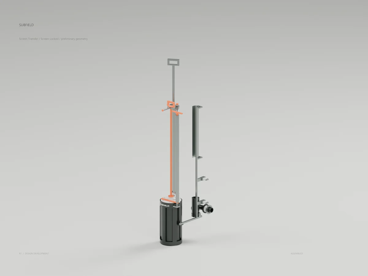
Research record
The detail behind
the study.
Source-linked work for this revision. Reported checks describe the stated model or test; physical qualification and applicability to the current retrofit remain separate.
Subfield screen-transfer concept: a vented bridge, receiver, partition interface and opening service guide. Original Subfield identity on actual CAD.
93 raw parts and 154 passing CAD tests. These are preliminary designs; operating performance and manufacturing release remain in development.
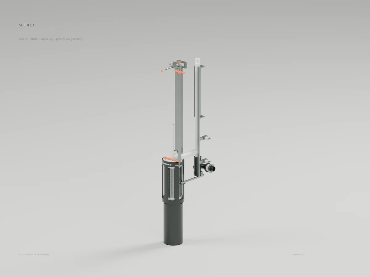
Connected transfer candidate
Captured screen / bridge removed
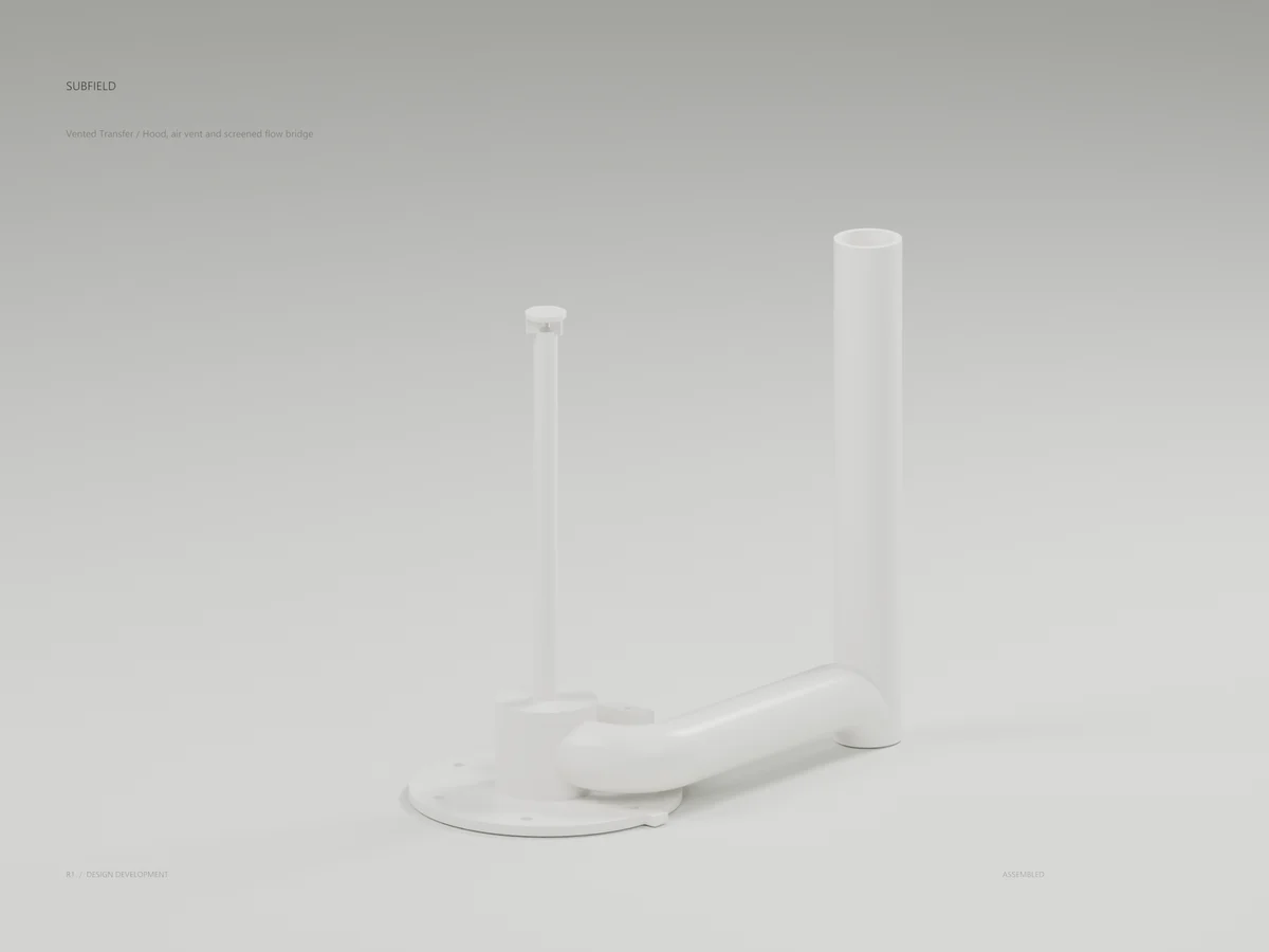
Vented hood and flow bridge
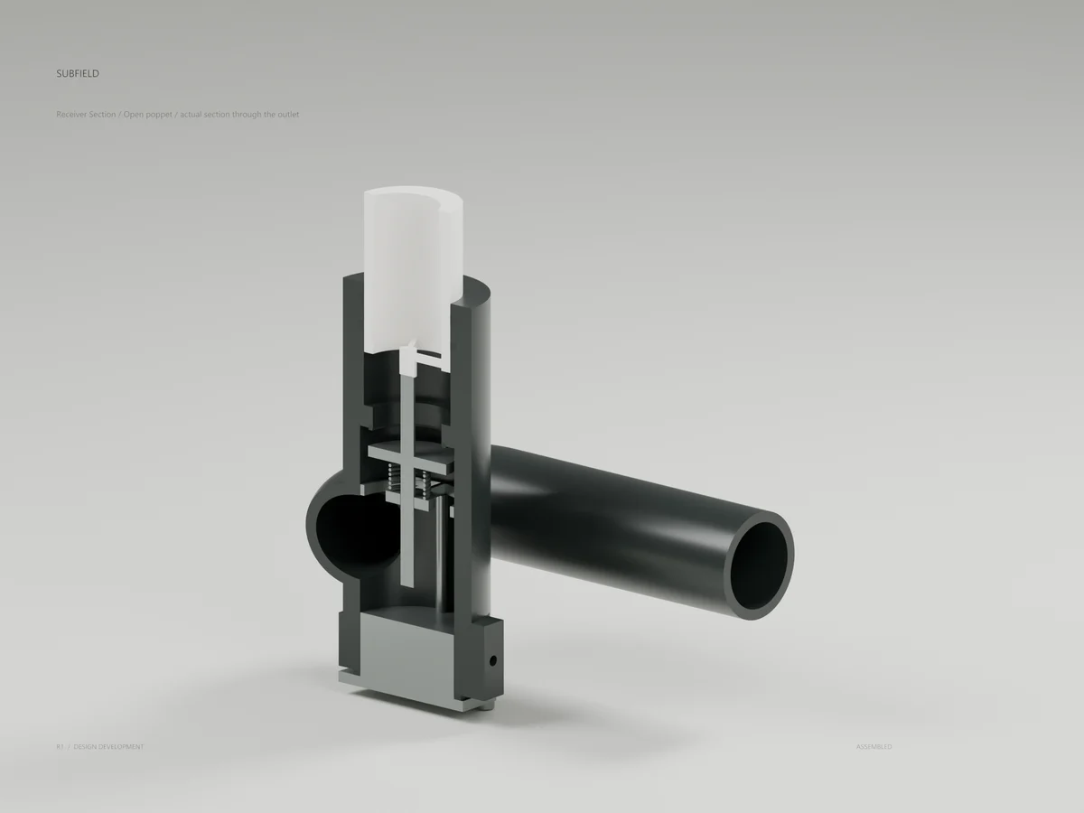
Receiver / actual open section
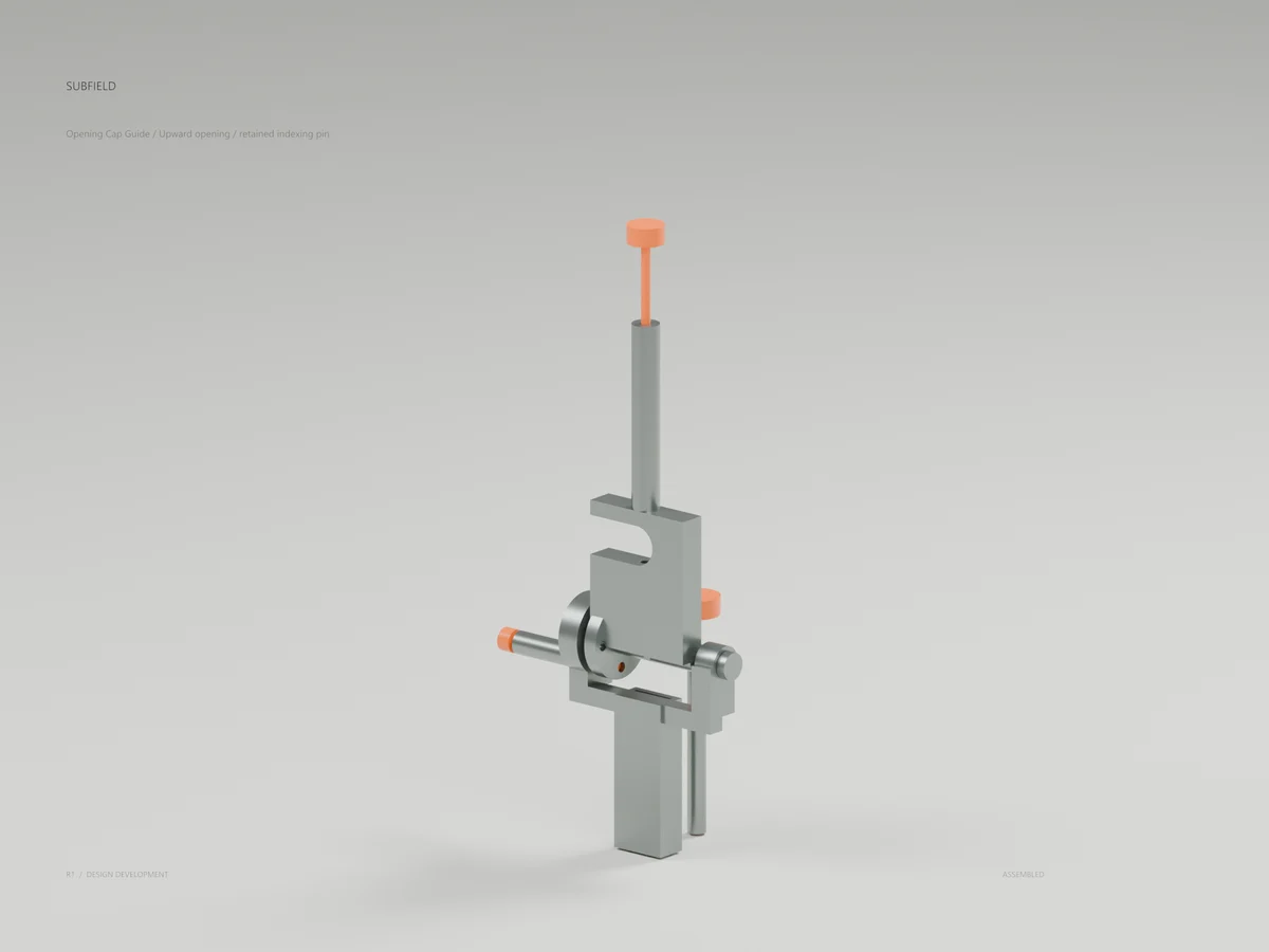
Opening cap guide / indexed at grade
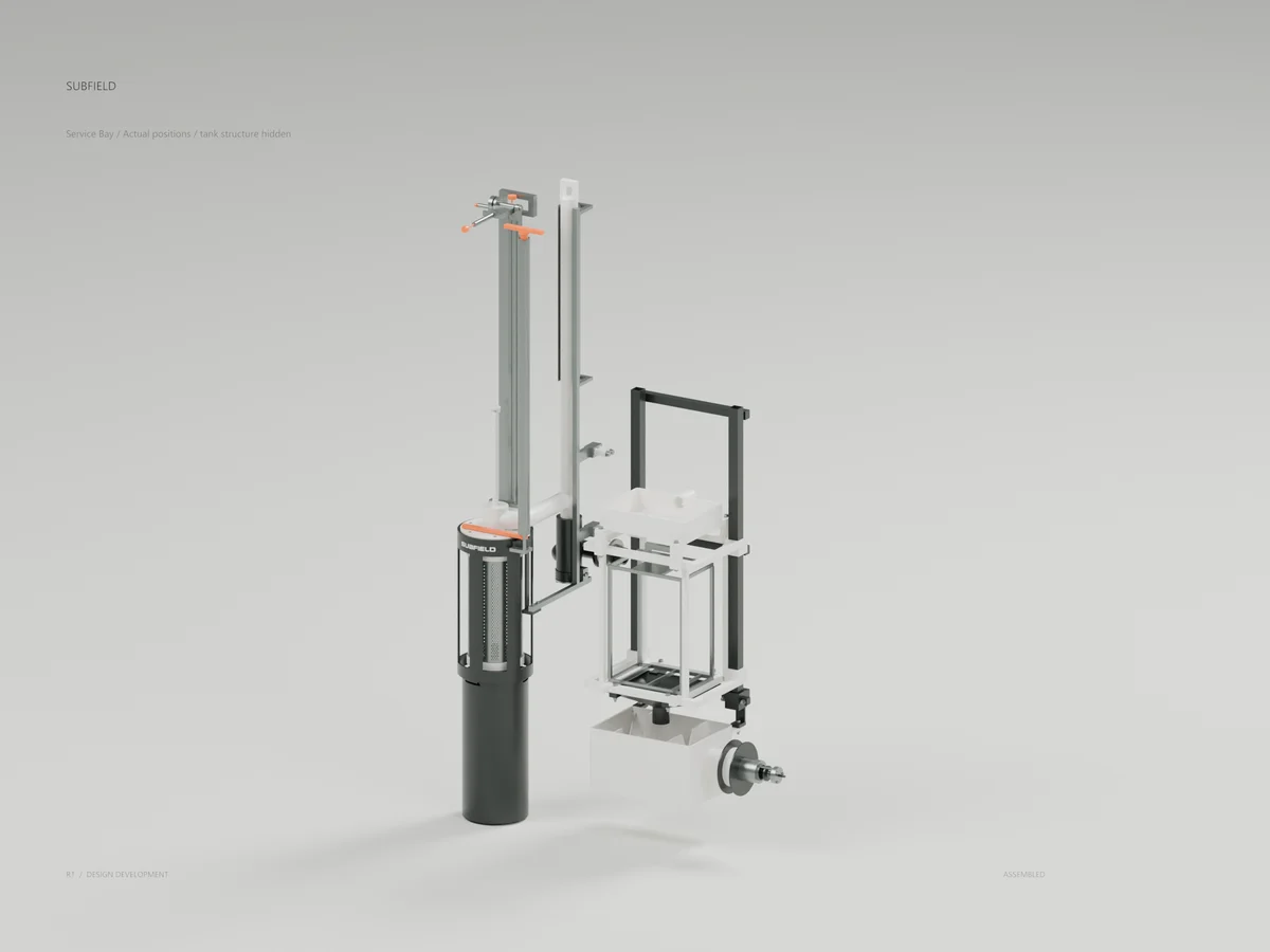
Service bay / actual tank positions
CONCEPT development package: 93 raw part STEP files, three separate-solid assembly states, eight assembly scenes, three actual CAD detail sections, six Subfield studio renders, GLB/Blender files, a six-page PDF and the 2485-body complete shallow-tank fit candidate. The service-bay render retains actual module positions and hides the tank structure for inspection.
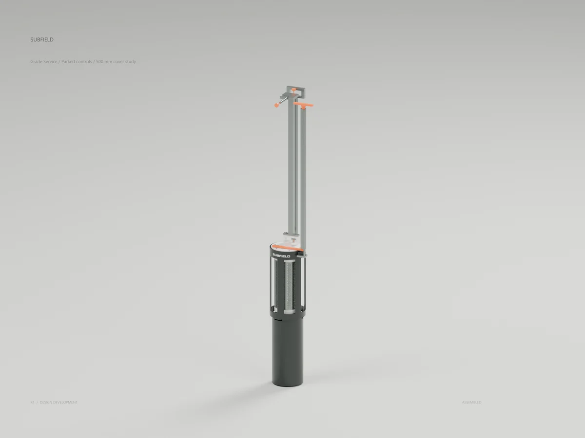
The removable bridge has a low hood, 32 mm conduit, headspace vent, probe and tubular handle. A fixed spring-return receiver discharges northward through the separate P1 sleeve. Its bolted lower cap and removable guide cage provide an assembly path for the internal valve parts. A new backbone connects the housing, receiver, open-front guide and four partition anchors. The opening upper cap guide has a captive indexing pin and a grooved hinge pin. These shapes define preliminary interfaces; they are not released fabrication drawings, selected supplier products or proof of structural/sealing performance.
Nominal receiver closure is 6 mm. First receiver and hood seal exposure occurs at 8.4 and 10.4 mm, giving 2.4 and 4.4 mm geometric margins. Bridge lift is 1172 mm; captured-screen lift remains 1467 mm. Opening the cap guide and removing the bridge are separate from capping/capturing the screen. Geometry does not establish a safe physical procedure, bridge hold-down, cap-keeper detent, no-entry replacement, wet lifting or controlled drainage.
Verification: 154 complete CAD tests; 104 geometry/export checks; 15 tank-fit checks; STEP reimport and individual-body transport; full external extraction boxes with 30 mm allowance; existing media, receiver and cartridge allowances; actual CAD render/section review. Motion tests sample intermediate poses and are not a continuous multibody simulation. The expensive insert uses a filled conservative envelope for clearance development only; full exports and renders retain all 2,352 holes.
Flow ratings, restriction and storage response, spring/seat behavior, material/laminate selection, joints, welds, tolerances, free seals, anchor loads, service flushing, foul-water handling and deep-cover operation remain in development. See the review PDF for the finite-storage upper-bound example; it is not an allowable service time.
Source and revision record
Source: screen-transfer-r1/index.html
Source SHA-256: ac27c212f2ead4017342bed5270907ef8ebc276b4033d2fd864021f321220dfc
Geometry and images describe this development revision. Current product ratings and manufacturing release require separate qualification.
Keep exploring the research.
Treatment & service / Development study
Subfield UV · Service review R2
Inspect the separate two-solid handle correction candidate and the engineering limits behind it.
Treatment & service / Design study
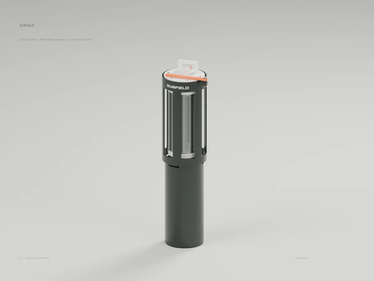
Coarse screen
A perforated cartridge, capture mechanism and contained-removal geometry.
Treatment & service / Design study
Screen grade controls
Long controls, capture hardware and the screen extraction arrangement.
Return to the current product.
Explore the retrofit-only platform and its compatibility, installation and service objectives.
Explore the retrofit