Engineering records / Engineering record / CORE-REAR-MOUNT-FIT-R1
Core Rear Mount Fit R1.
Geometry, analysis and remaining engineering work for Core Rear Mount Fit R1.
Retained development study. Dimensions, names and checks belong to this revision—not automatically to the retrofit-only product. Manufactured tank shells are deferred. No installation instruction, certification or manufacturing release is represented.
The source reasoning
Why this detail was investigated.
R7 passes nominal geometry checks, but all three examined sliding fits fall below the proposed prototype clearance targets after dimensional variation and coating. This analysis does not change the CAD or authorize fabrication.
Read the research and limitsResearch record
The detail behind
the study.
Source-linked work for this revision. Reported checks describe the stated model or test; physical qualification and applicability to the current retrofit remain separate.
Core rear mount: prototype fit budget R1
R7 passes nominal geometry checks, but all three examined sliding fits fall below the proposed prototype clearance targets after dimensional variation and coating. This analysis does not change the CAD or authorize fabrication.
| Interface | Nominal gap mm | Worst-case gap mm | Proposed target mm | Result |
|---|---|---|---|---|
| head entry (radial / each side) | 0.300 | 0.085 | 0.100 | Below target |
| slot travel (radial / each side) | 0.300 | 0.085 | 0.100 | Below target |
| head-to-shoulder throat (total axial) | 0.300 | 0.050 | 0.200 | Below target |
The head and slot calculations subtract half the opening/member size stack, 0.10 mm relative center error, 0.05 mm carrier coating and 0.025 mm stud coating. The axial calculation subtracts both dimensional tolerances and coating on both opposing faces of each component. No statistical cancellation is assumed.
These are proposed budgets for a machined prototype, not demonstrated process capability. Relative center error is an assembled-pattern allocation; individual stud location, hole location, rotation and fixture error must together remain within it. Burrs, form error, thermal movement, dirt and elastic deflection have no additional allowance here. The positive residual gap therefore does not prove reliable assembly or outdoor service.
Under these exact assumptions, entry diameter and slot width each need at least 0.03 mm additional size, and the stud neck needs at least 0.15 mm additional length, merely to reach the proposed targets. The next geometry revision should include reserve and recheck wall clearance, thread engagement, stud retention and the complete release path. Changing the neck cannot be treated as an isolated dimension change.
Source and revision record
Source: core-rear-mount-fit-r1/READ-ME.md
Source SHA-256: df5a2bfa142d7bf7b5d20bb713140e53a98c2a3a36805b939bcddf6146faeed5
Geometry and images describe this development revision. Current product ratings and manufacturing release require separate qualification.
Keep exploring the research.
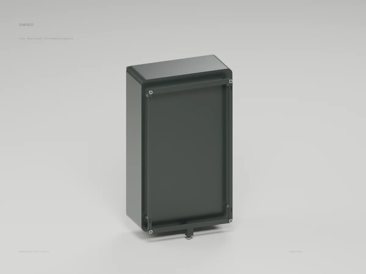
Engineering records / Engineering record
Core Lock Clearance R10
Geometry, analysis and remaining engineering work for Core Lock Clearance R10.
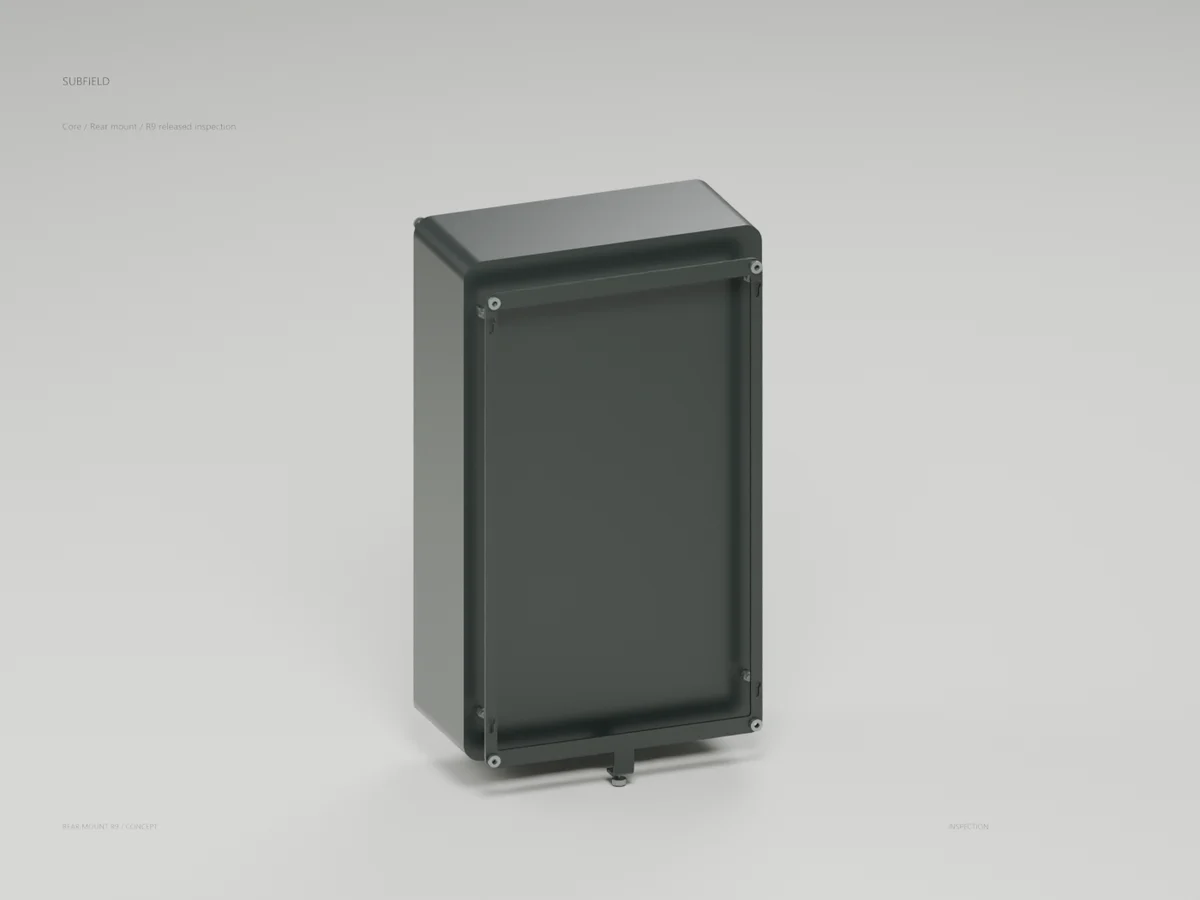
Engineering records / Engineering record
Core Carrier Formed R9
Geometry, analysis and remaining engineering work for Core Carrier Formed R9.
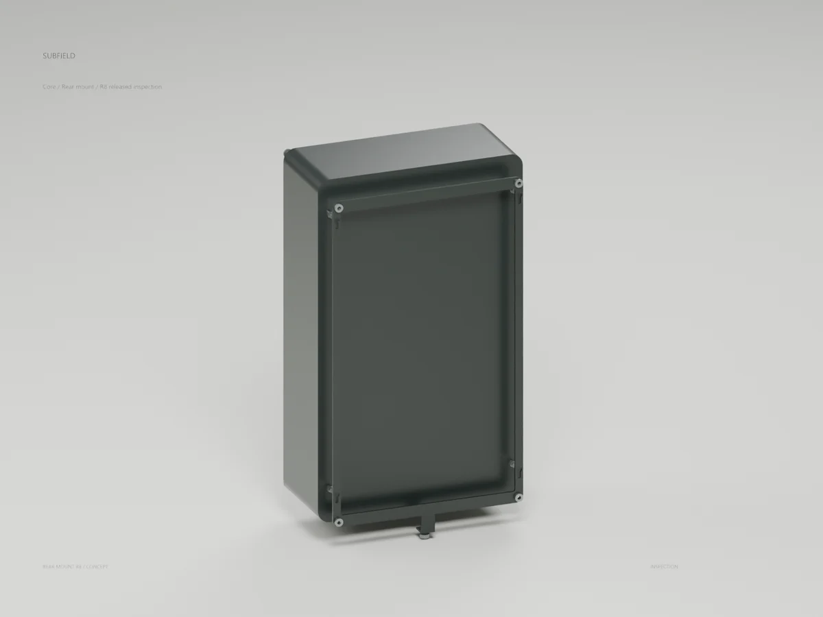
Engineering records / Engineering record
Core Rear Mount R8
Geometry, analysis and remaining engineering work for Core Rear Mount R8.
Return to the current product.
Explore the retrofit-only platform and its compatibility, installation and service objectives.
Explore the retrofit