Engineering records / Engineering record / CORE-BARRIER-STUDY
Core Barrier Study.
Geometry, analysis and remaining engineering work for Core Barrier Study.
Retained development study. Dimensions, names and checks belong to this revision—not automatically to the retrofit-only product. Manufactured tank shells are deferred. No installation instruction, certification or manufacturing release is represented.
The source reasoning
Why this detail was investigated.
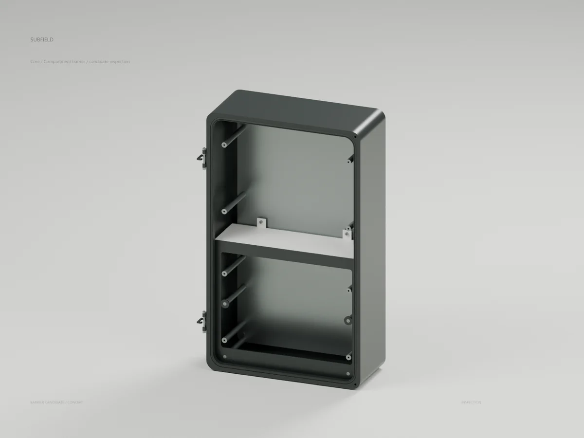
73-part mechanical candidate retaining the current exterior. A removable lower front frame seats the power cover. Fixed rear and side barriers meet the tray and divider; a tray rib and rounded divider ends permit rotation behind the frame. Four removable bezel posts replace fixed arms that obstructed tray withdrawal.
Read the research and limitsResearch record
The detail behind
the study.
Source-linked work for this revision. Reported checks describe the stated model or test; physical qualification and applicability to the current retrofit remain separate.
Subfield Core compartment barrier study
73-part mechanical candidate retaining the current exterior. A removable lower front frame seats the power cover. Fixed rear and side barriers meet the tray and divider; a tray rib and rounded divider ends permit rotation behind the frame. Four removable bezel posts replace fixed arms that obstructed tray withdrawal.
Evidence: - 943 nominal fit/export checks pass, including 73 separate valid STEP solids. - 1,720 conservative service-motion/tool checks pass: front-frame extraction, divider rotation/extraction, post removal with an assumed D16 socket envelope, then tray/support withdrawal. - The ideal CAD void calculation separates a sample in the closed power compartment from samples in the upper compartment and ahead of the lower cover. Removing the lower cover reconnects them as a negative control. - Actual CAD render/native Blender reopen verifies 54 visible meshes. The weather cover and faceplates are intentionally omitted for inspection.
Nominal service sequence: isolate the assembly; remove weather cover and faceplates with their loose hardware; remove four countersunk frame screws and withdraw the frame; remove divider screws, rotate the divider 20 degrees and withdraw it; unscrew/remove four frame posts; remove tray screws and withdraw the tray/support carrier. Unlike R5, this divider rotates before any outward pull. Thread rotation/torque, real tools, hands, electronics and wiring remain unqualified.
Post axes: X +/-144, Y -150/-273. Post body Z13..130 with AF10 drive at Z120..130; nominal M4 lower stud Z9..13 and upper blind bore Z122.4..130. The housing receivers are blind. Generic countersunk screws seat 0.1 mm below the frame surface. Tray corners are R16; the divider has semicircular R1.5 plan ends. These are development dimensions, not fabrication tolerances.
The connectivity result assumes ideal zero-gap CAD contacts; it proves no electrical rating, sealing, touch protection, creepage or dielectric performance. The many small void components include nominal fastener cavities and are not separate functional compartments. Materials, process, tolerance stack, anti-loosening, thread/preload/stiffness, actual wiring penetrations, supplier parts, thermal behavior and physical qualification remain open. Rear-carrier attachment is still absent. This study is outside the R4/R5 regression scope and is not fabrication-ready.
Scripts are workspace-relative development source. They depend on the accompanying workspace CAD modules; integration and a portable reproducible release package remain to be completed.
Source and revision record
Source: core-barrier-study/READ-ME.md
Source SHA-256: 1838093b9507a8e3c1a272857505df71fcd60dc93f39b44b37dd72aaf2cd63c4
Geometry and images describe this development revision. Current product ratings and manufacturing release require separate qualification.
Keep exploring the research.
Engineering records / Engineering record
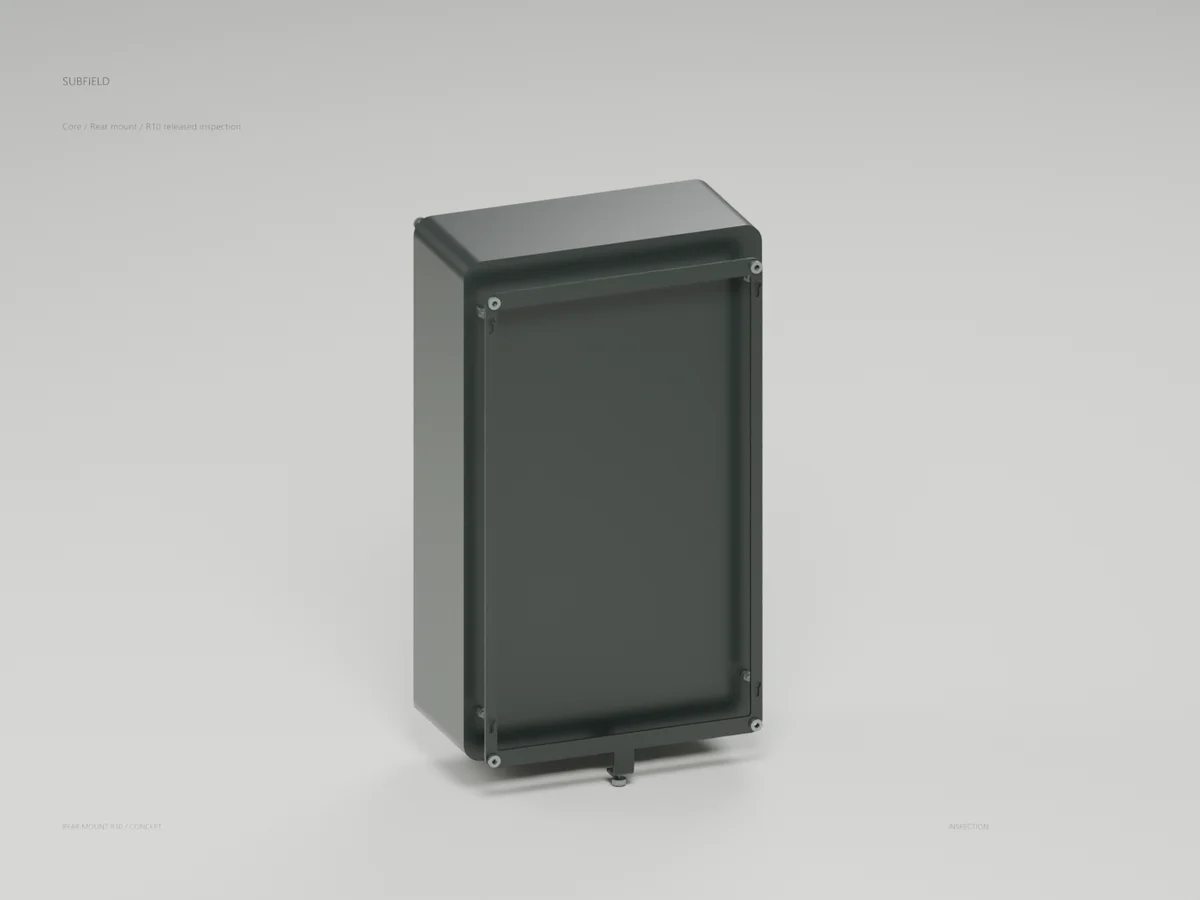
Core Lock Clearance R10
Geometry, analysis and remaining engineering work for Core Lock Clearance R10.
Engineering records / Engineering record
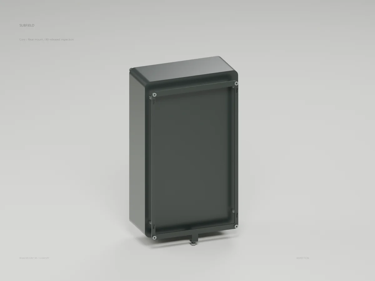
Core Carrier Formed R9
Geometry, analysis and remaining engineering work for Core Carrier Formed R9.
Engineering records / Engineering record
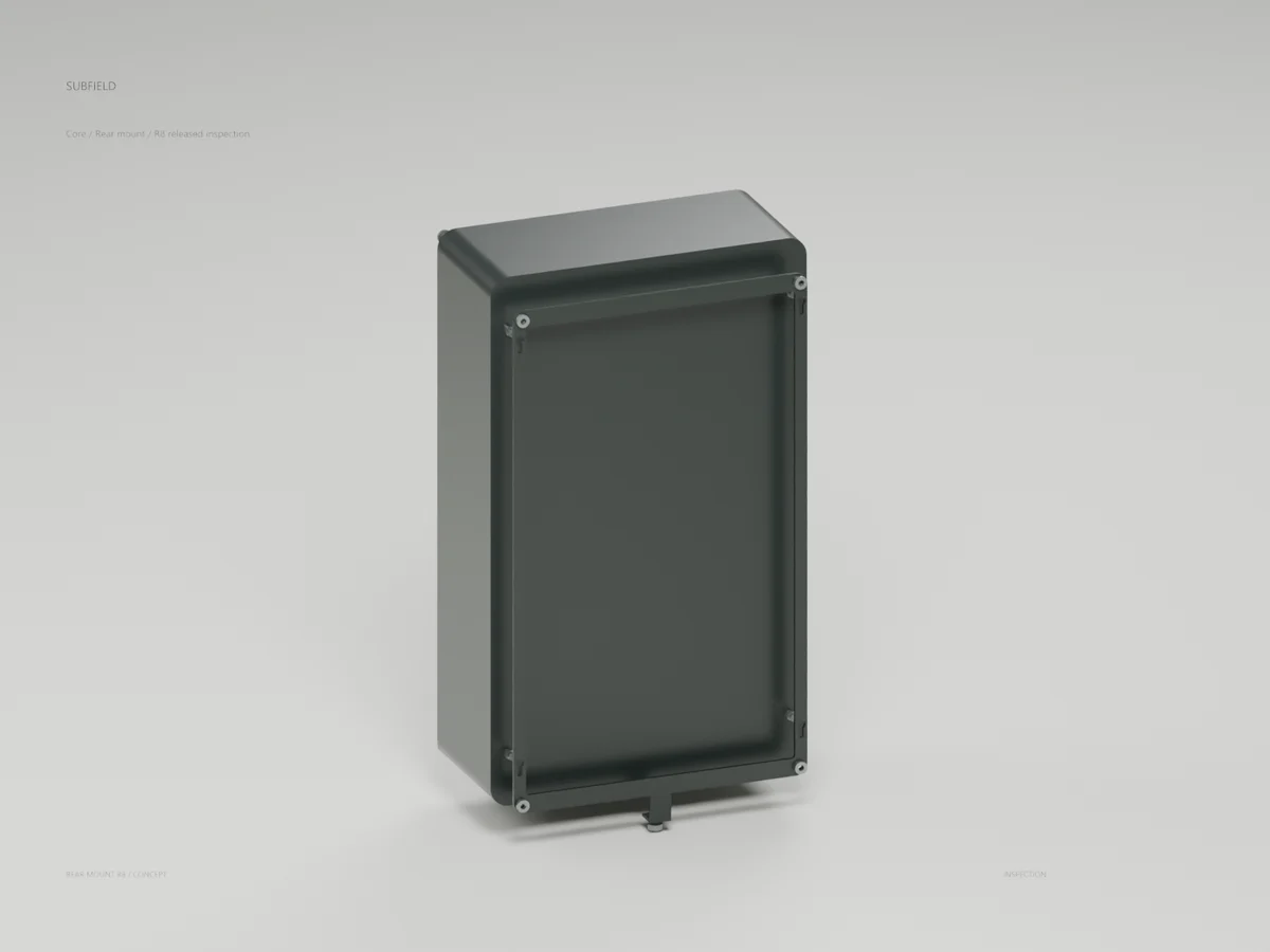
Core Rear Mount R8
Geometry, analysis and remaining engineering work for Core Rear Mount R8.
Return to the current product.
Explore the retrofit-only platform and its compatibility, installation and service objectives.
Explore the retrofit