Controls / PCB placement study / CONTROLLER-ELECTRONICS-R21
Control, considered at board level.
Explore the proposed controller board, its channel layout and its place inside the cabinet.
Retained development study. Dimensions, names and checks belong to this revision—not automatically to the retrofit-only product. Manufactured tank shells are deferred. No installation instruction, certification or manufacturing release is represented.
Inside the controller / R21
Explore the board.
Select an area to locate it in the placement model. Open its explanation to see the design intent and remaining work.
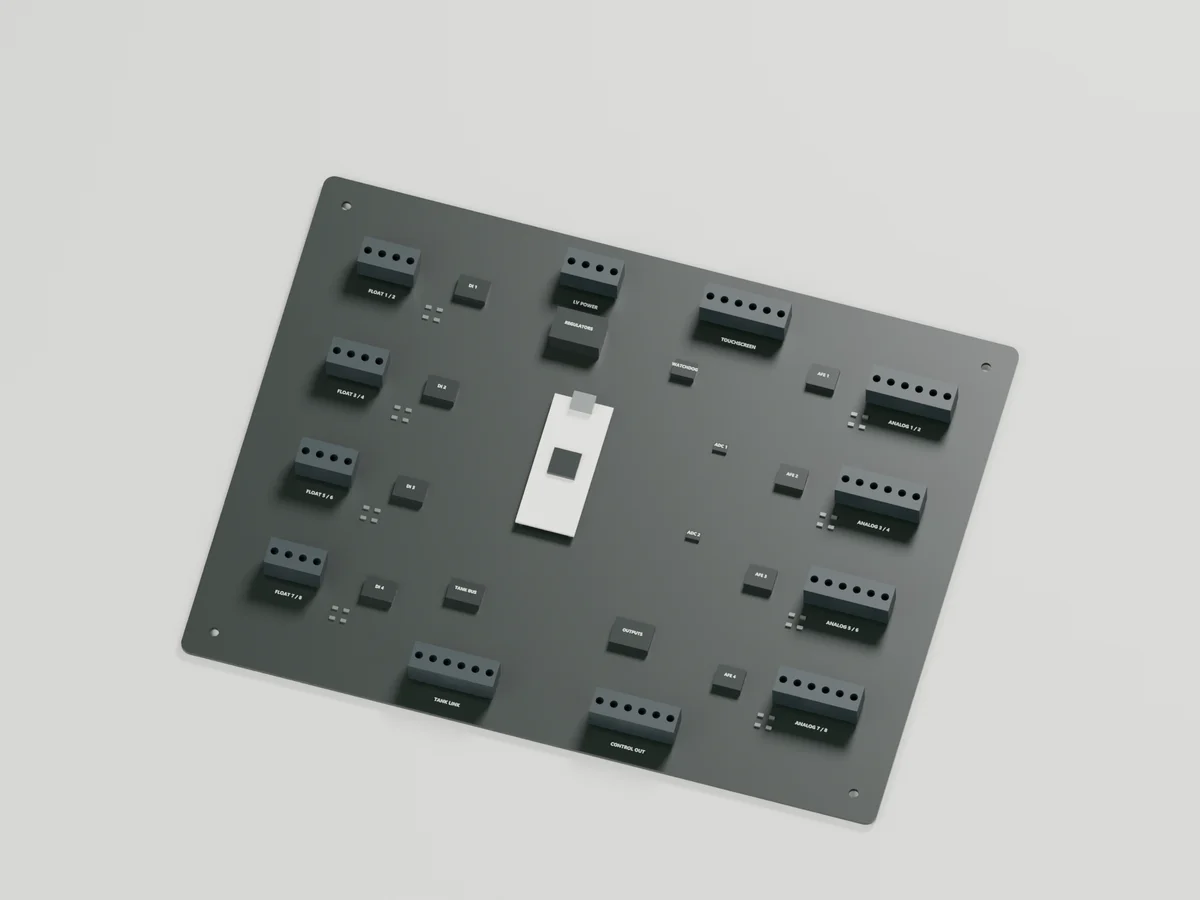
250 × 190 mm proposed outline. Package shapes reserve space; they are not verified supplier footprints. No routed copper or manufacturing files are released.
8 contact inputs — design intent
Give every contact a defined role.
Eight proposed float or contact channels reserve room for input conditioning between field connections and processor logic. A contact state needs an assigned process meaning before it can inform control.
Why it matters. Separating the field interface from logic lets protection, wiring faults and signal quality be addressed deliberately. Production circuits and line supervision remain to be designed.
8 analog inputs — design intent
A measurement starts before the ADC.
Eight proposed analog channels place sensor-specific front ends ahead of two candidate ADS1115 converters. Those devices sample channels in sequence; they do not provide simultaneous sampling.
Why it matters. A level transmitter and a raw chemistry probe need different conditioning. Range, grounding, protection, calibration and any required isolation depend on the selected sensor. Field signals cannot connect directly to this placement model.
Local logic — design intent
Keep control close to the system.
The central module reserve gives deterministic control logic a place on the board. A separate USB-powered Pico 2 bench exercise uses switches and LEDs to explore input handling and command behavior.
Why it matters. Local control must make deliberate decisions from valid inputs. The bench exercise is not production firmware and has not been exercised on physical hardware; the final processor and board port remain open.
4 command outputs — design intent
Command the switch. Keep power separate.
Four proposed low-voltage channels are allocated to control and alarm commands. Pump line current belongs in a separately rated switching assembly fixed inside the cabinet.
Why it matters. The processor should not carry pump power. Default-off states, independent inhibit, feedback and fault detection still need an electrical design matched to the actual actuators.
Tank link — design intent
Know when the connection is lost.
A reserved interface connects the controller to the protected tank power and data trunk. Its bus, conductors, connectors, grounding and isolation must be designed together.
Why it matters. A severed trunk removes remote power and sensing. The controller must show that loss instead of presenting stale measurements as healthy. Raw GPIO and I²C are not proposed field-cable interfaces.
Supply + supervisor — design intent
Watch the supply. Define the fallback.
Low-voltage power, regulation and supervisor areas are reserved near the upper board edge. Incoming supply protection, conversion and pump switching remain fixed in the cabinet.
Why it matters. Brownouts and processor faults need defined behavior beyond a software heartbeat. Independent watchdog, inhibit and alarm reserve remain engineering requirements, not features proven by this model.
Local interface — design intent
An interface to control, with clear limits.
The proposed touchscreen sits below the board on the inside of the same door. It would show input quality, alarms, command versus feedback, connection health and service information.
Why it matters. The display requests actions through control logic; it must not bypass protective interlocks. Display hardware, protocol and the restrained door service loop still require selection and integration checks.
From placement to a working board.
This model establishes an arrangement to review. The schematic is incomplete and PCB routing has not started. Equipment selection, verified footprints, circuit review, prototype assembly and physical fault testing are still ahead.
The source reasoning
Why this detail was investigated.
Separating low-voltage sensing and commands from fixed power hardware gives each part a defined role. This 250 × 190 mm placement study starts the custom PCB design; it does not establish a routed or tested board.
Read the research and limits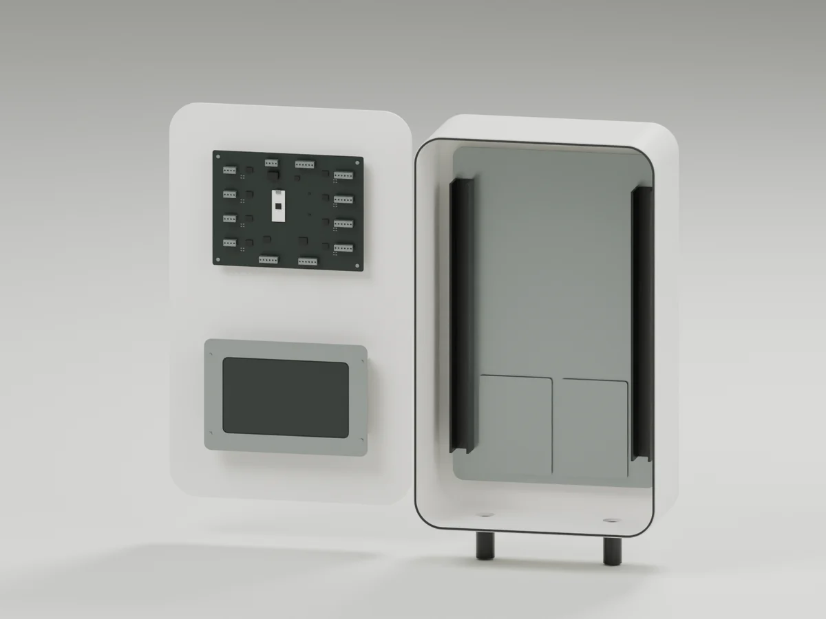
Research record
The detail behind
the study.
Source-linked work for this revision. Reported checks describe the stated model or test; physical qualification and applicability to the current retrofit remain separate.
Custom I/O board placement, integrated cabinet model and a low-voltage breadboard test package.
Development package — not a complete electrical design. The schematic, PCB routing, final component selections, pump-power circuit and physical qualification remain unfinished. Package blocks are placement reserves, not a released populated PCB.
Custom board placement
250 × 190 mm. Eight float/contact channels, eight proposed conditioned analog channels, tank link, output stages, local service, HMI and supervisory areas. 164 modeled parts.
Inside the same cabinet
The board occupies the upper inside of the door, with the touchscreen and its retaining frame below. The fixed backplate and bottom conduits remain accessible. This is a spread-open inspection pose.
Build the bench concept
USB-powered Pico 2, eight local switches and four indicator LEDs. Optional potentiometers and two ADS1115 breakouts extend analog testing. No pump power or field wiring on the breadboard.
MicroPython bench runner · Bench logic · Optional ADC exercise
Seven host tests passed for the logic and ADC command handling. Hardware execution, timing, wiring and electrical performance have not been tested physically.
Touchscreen feature layout
Proposed information architecture below. This is not connected to hardware and is not deployed touchscreen software.
System overview
The HMI requests actions from deterministic control logic. It must not directly bypass protective interlocks or treat stale tank data as healthy. Exact sensor profiles, thresholds and approved control behavior remain to be specified.
Work required before fabrication
Confirm pump ratings, sensor models, channel counts and touchscreen choice.
Complete input protection, analog conditioning, bus, output, power and watchdog schematics.
Select and verify footprints, connector pin assignments and supplier 3-D models.
Route and review the PCB; verify clearances, thermal behavior, power integrity and EMC design.
Build prototypes and perform electrical, fault, firmware, environmental and enclosure tests.
Source basis: Raspberry Pi Pico documentation , Pico pinout , TI ADS1115 , TI ISO1212 .
R24: actual door rotation and hinge-location checks
Source and revision record
Source: controller-electronics-r21/index.html
Source SHA-256: 2aacc3093371a4ae91459f3f7cb6cf7672456ad8593f1b0f3f60d6c667b5bb83
Geometry and images describe this development revision. Current product ratings and manufacturing release require separate qualification.
Keep exploring the research.
Controls / Design study
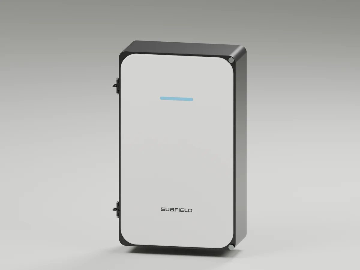
Control fascia attachment
Controller and alarm face studies with visible service hardware.
Controls / Design study
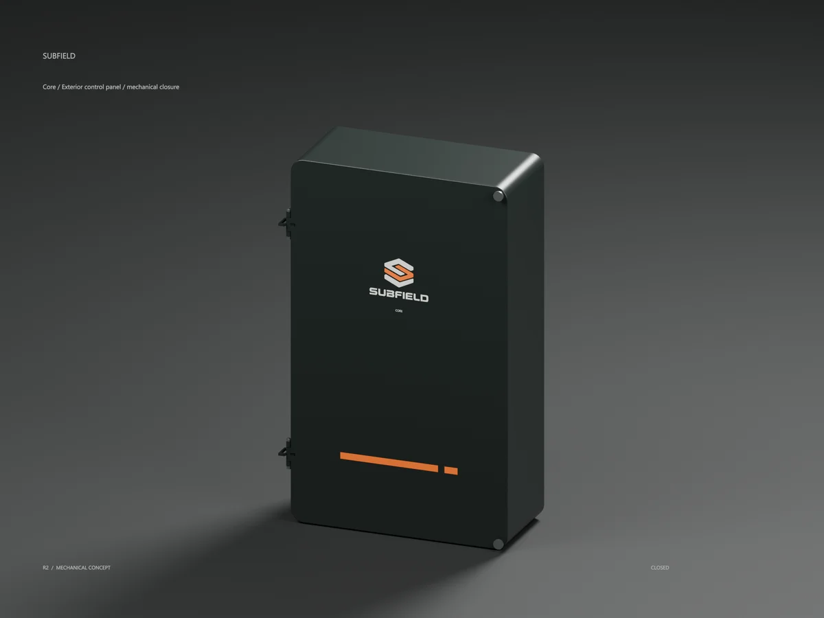
Core enclosure mechanics
Seal groove, captive closure and a pinned cover for the exterior Core enclosure.
Controls / Current architecture / mechanical interface
Control platform
Industrial supervision, deterministic tank control and reusable PoE sensing. Fixed carriers replace the oversized moving-board direction.
Return to the current product.
Explore the retrofit-only platform and its compatibility, installation and service objectives.
Explore the retrofit